Contact
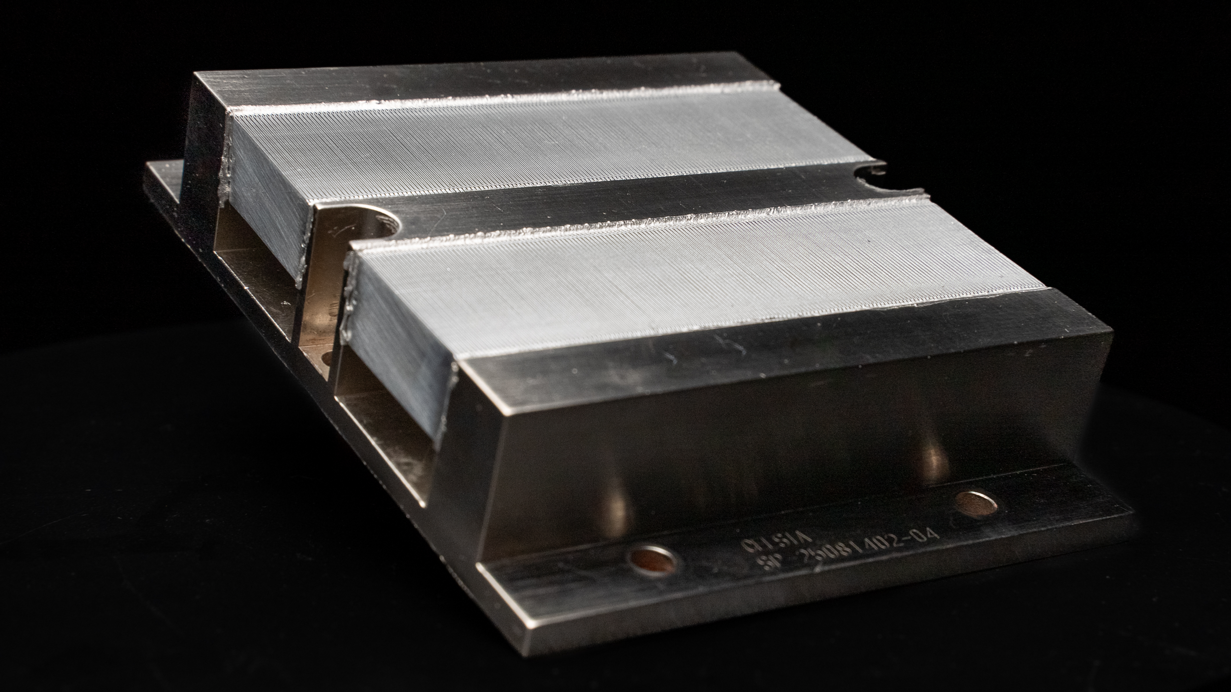
JouleForce vapor-chamber cooler on black
The product · JouleForce platform

One cooling core.
Every integration point.

JouleForce is a patented, air-based cooling platform built around a microchannel core architecture. Forced Physics configures that core for chip sockets, server chassis, rack demonstrations and specialized edge systems, then fabricates a POC for customer evaluation.

Cooling medium
Air
Core architecture
Microchannel array
Target power envelope
500–2,000 W+
Evaluation model
Custom POC
JouleForce Air · the cooler

Performance lives in the geometry.

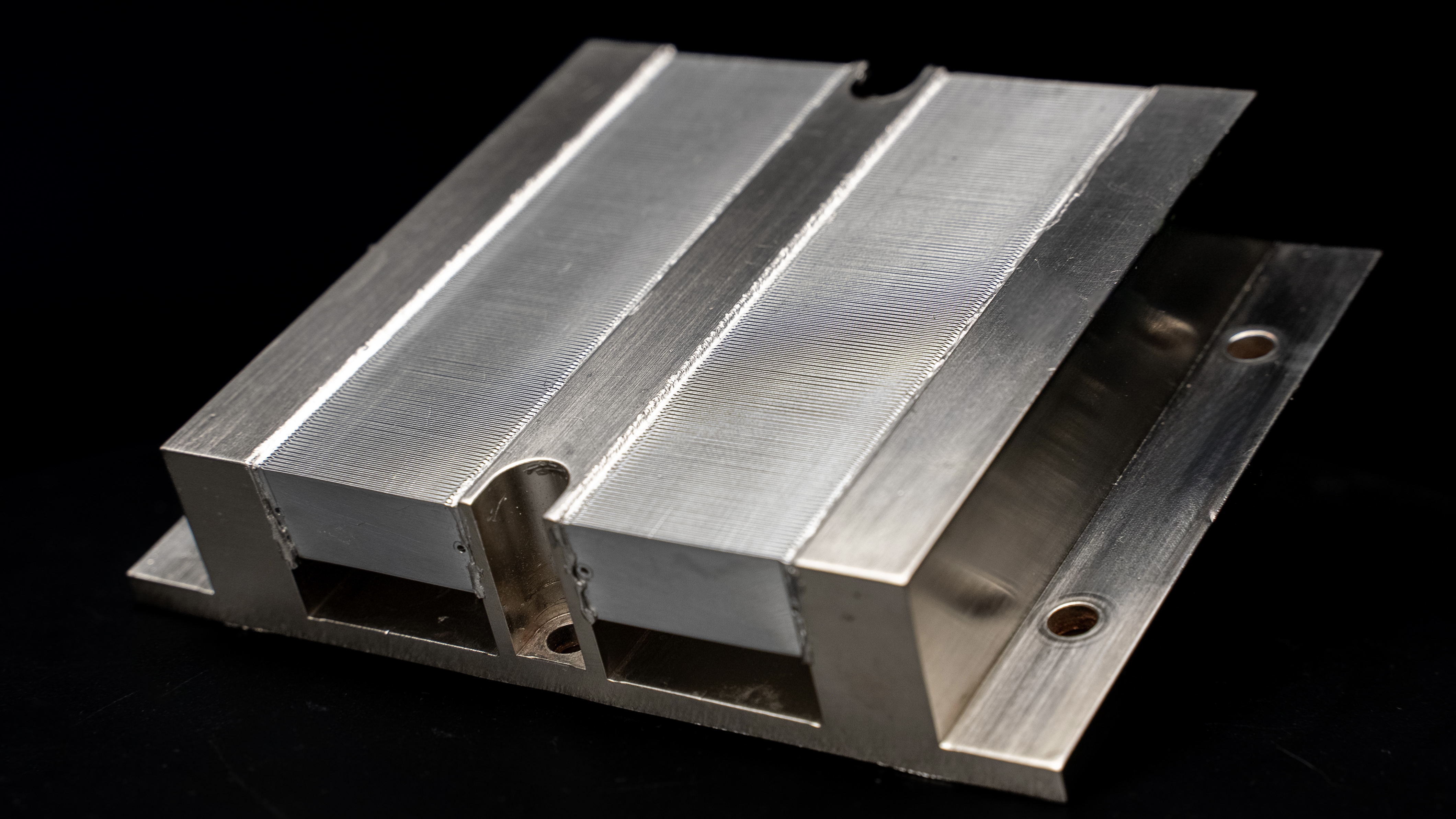
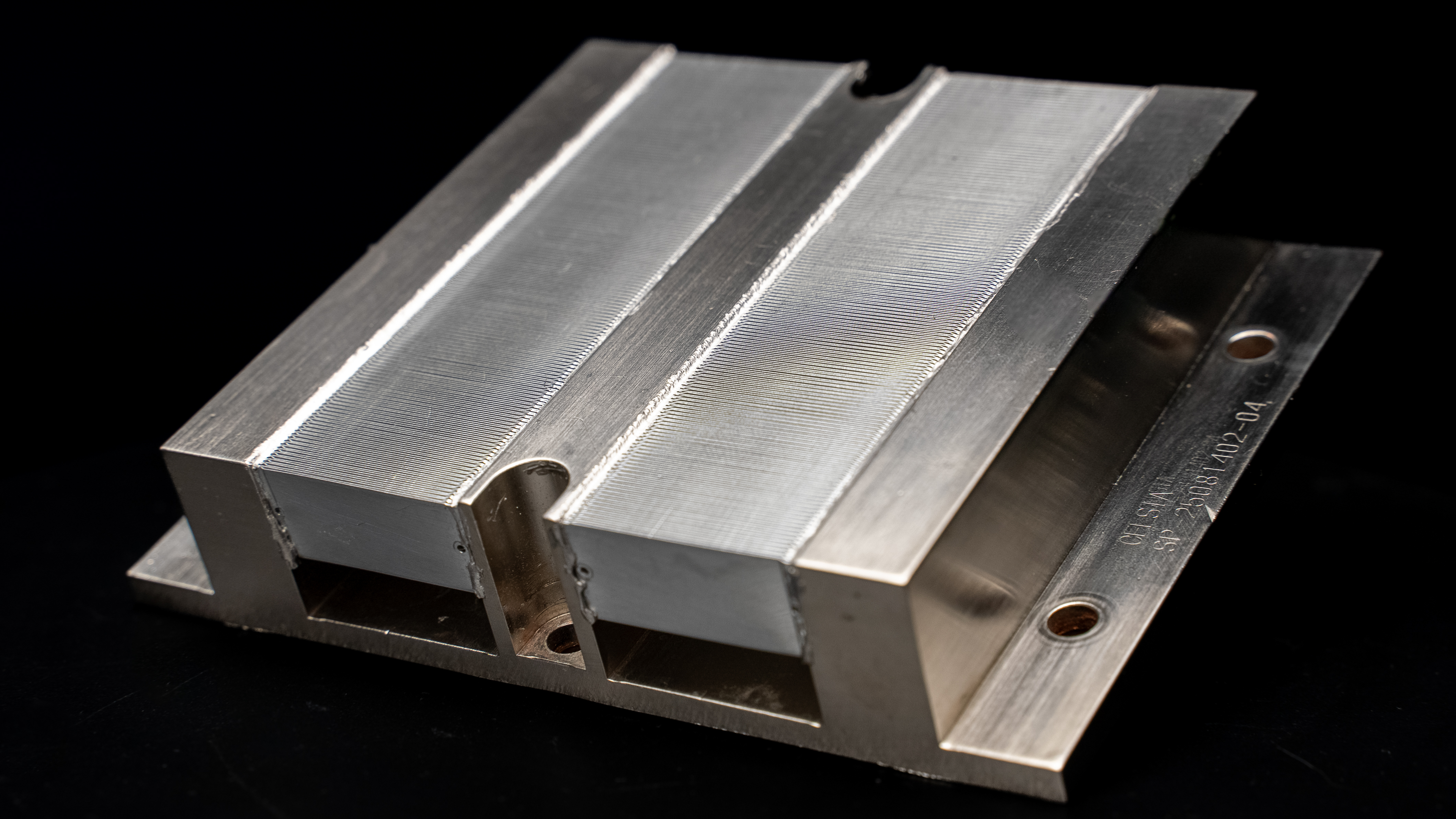
A sealed vapor chamber houses the patented microchannel array, made to fit individual sockets. There is no pump, no manifold, no liquid, and nothing to leak. The heat-removal pathway is directly from the chip into the outside environment with no extra steps.

Three-quarter view of the JouleForce Air cooler showing dual microchannel arrays JFA · SP5
Microchannel array
Patented microchannel geometry drives heat removal inside the channel.
Airflow path
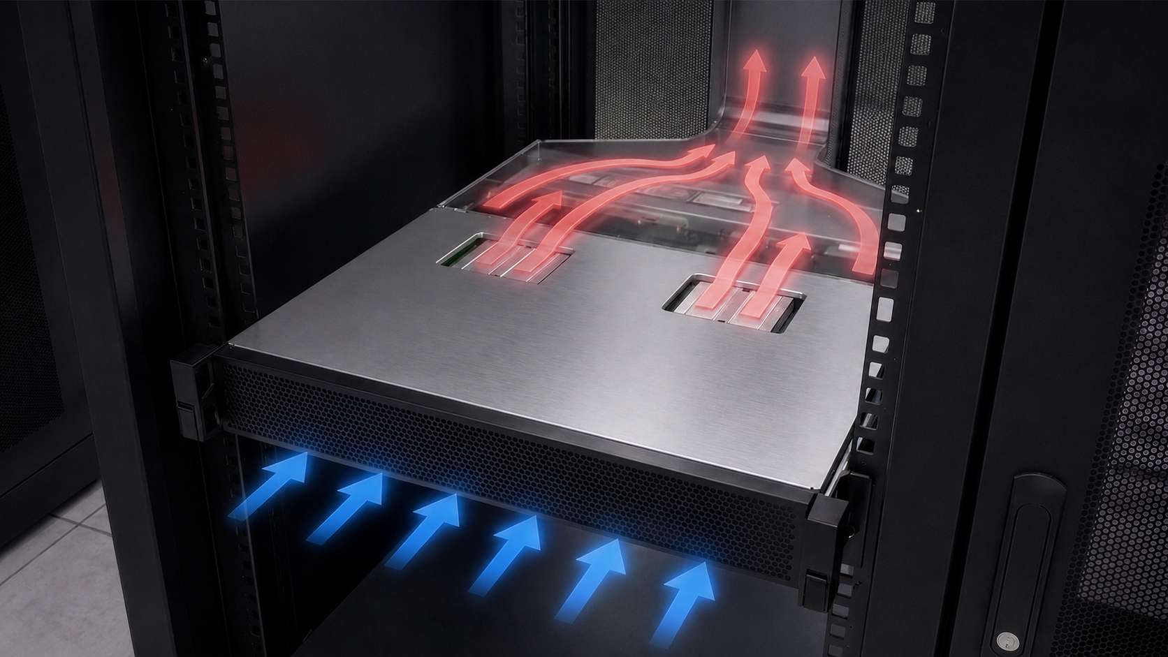
A fan or blower maintains a pressure differential across the array, pulling air in through the inlet ports at the base and exhausting it upward through the microchannel array.
Mounting base
Engineered to fit the target socket envelope.
Construction
Socket Specific
Two-phase vapor chamber with aluminum microchannel array.
Moving parts in core
None
External fan or blower provides airflow.
Airflow required
~1/3 of reference
Versus the conventional air baseline at equal load.
See it in motion

The JouleForce Air cooler, in full.

A precision vapor chamber, made to fit individual sockets, every microchannel and mounting surface, captured in one continuous view.

Product configurations

One core. Configured for each layer.

The JouleForce core is adapted to each integration point, from a chip socket-specific cooler to a server chassis model, rack demonstration, or specialized edge system.

JouleForce chip-level cooler 01 · At the chip
Direct-to-chip

Designed for the target package

A custom cooler engineered around the target chip socket, package, power envelope, airflow and mounting constraints.

Engineered for the target socket or package
Validated against measurable thermal targets
Path to reference design and licensing
Scope a Socket POC →
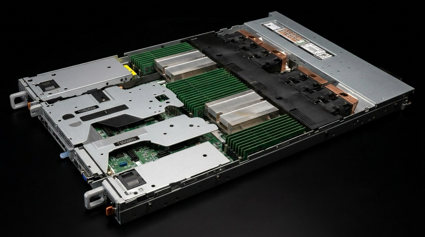
A 1U dual-socket server, shown at an angle on black, with two JouleForce coolers installed over the CPU sockets between the DIMM banks 02 · In the chassis
OEM server integration

Built with the OEM platform

A chassis-integrated POC developed around airflow, mechanical envelope, service requirements and live-compute validation.

No external liquid loop or CDU
Designed around chassis airflow and packaging
Path to OEM integration and design in
Scope an OEM POC →
Rack-level diagram: a JouleForce server sled drawing cool air in through the front and exhausting hot air up through the microchannel array into a rear vertical exhaust plenum 03 · Across the rack
Rack & data center

Validate at rack scale

An instrumented deployment combining JouleForce coolers, airflow, exhaust and facility interfaces.

Jointly scoped demonstration
Measures thermal, energy and compute performance
Informs greenfield, retrofit and broader deployment
Scope a rack demonstration →
JouleForce edge enclosure deployed at a remote off-grid site with a cell tower, wind turbines, and solar panels at sunset 04 · At the edge
Compact & remote

Engineered for constrained environments

Designs for remote, sealed, or application-specific systems with constrained cooling infrastructure.

Application-specific thermal design
Outside or conditioned-air configurations
Designed for field or remote deployment
Discuss a custom design →
Technical specifications

JouleForce Array, at a glance.

Representative specifications for the core cooler. Final geometry and performance are defined for each target platform and validated through a customer POC.

Cooling approach
Direct-to-chip, air-based
Core architecture
Patented microchannel array geometryIssued patent portfolio · array geometry and implementation
Target heat load
Scales with microchannel count. The array is engineered to the target socket envelope and TDP. More microchannels deliver more cooling capacity without changing the underlying architecture.Socket-specific configurations available. Contact for platform evaluation.
Thermal resistance
50% lower than a conventional air heatsink at one third the airflow rate Compared to 1U Dell heat sink under matched test conditions, Villanova LATFS
Liquid infrastructure
None. No CDUs, manifolds, hoses, or coolant.
Materials
Sealed two-phase vapor chamber, aluminum microchannel
Mounting
Engineered for target socket envelope. Platform-specific validation required.
How we engage

From target hardware to a validated product.

Every engagement starts with the customer's hardware and ends with measured performance and a defined path to integration.

Step 1
Scope

Define the
target

Document the socket or package, power envelope, airflow, mechanical constraints, operating environment, and required outcomes.

Step 2
Design and fabricate

Build the
POC

Engineer the cooler, mounting, and airflow path, then fabricate a platform-specific prototype for evaluation.

Step 3
Test and validate

Measure on real hardware

Compare thermal and compute performance against the customer's baseline under agreed test conditions.

Step 4
Integrate, commercialize

Define the next product step

Advance toward a reference design, OEM integration, licensing agreement, custom system, or rack demonstration.